
PRTG Manual
SIMATIC S7-300/400 Custom Process Data Sensor
The SIMATIC S7-300/400 Custom Process Data sensor monitors process data of a SIMATIC S7-300 or S7-400 Programmable Logic Controller (PLC) via the S7 protocol. It reads values from data blocks, process image inputs, and process image outputs.
 This sensor is in beta status. The operating methods and the available settings are still subject to change. Do not expect that all functions work properly, or that this sensor works as expected at all.
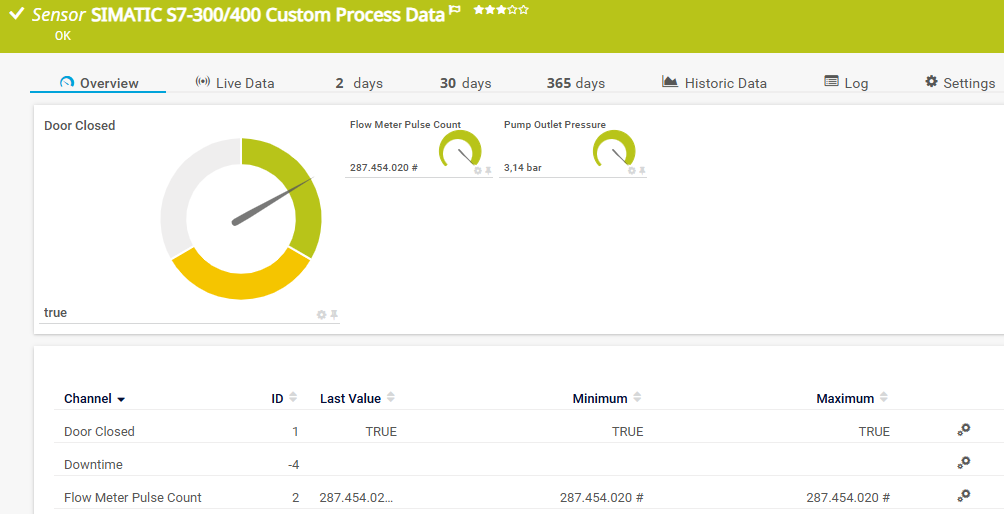
SIMATIC S7-300/400 Custom Process Data Sensor
 For a detailed list and descriptions of the channels that this sensor can show, see section Channel List.
- Dutch: SIMATIC S7-300/400 Custom Process Data
- French: SIMATIC S7-300/400 Custom Process Data
- German: SIMATIC S7-300/400 Custom Process Data
- Japanese: SIMATIC S7-300/400 Custom Process Data
- Portuguese: SIMATIC S7-300/400 Custom Process Data
- Russian: SIMATIC S7-300/400 Custom Process Data
- Simplified Chinese: SIMATIC S7-300/400 Custom Process Data
- Spanish: SIMATIC S7-300/400 Custom Process Data
Consider the following remarks and requirements for this sensor:
Requirement |
Description |
|---|---|
This sensor requires that the Beta Sensors experimental feature is enabled.
|
|
Credentials |
This sensor requires connection settings for Siemens S7 in settings that are higher in the object hierarchy. |
Parent device |
This sensor requires that the parent device is a Siemens S7-300 or S7-400 programmable logic controller. |
IPv4 |
This sensor only supports IPv4. |
Performance impact |
This sensor has a very low performance impact. |
Lookups |
This sensor can use lookups. Select Lookup (default) as Display Channel #x As and select the lookup in Channel #x Lookup. The sensor is not intended to work with default lookups, so you should create your own custom lookup. |
Connection errors |
If the sensor shows a connection failure error message, such as Connection timed out, Unreachable peer, or Connection refused, make sure that the values you defined in the port, rack, and slot settings in the Connection Settings for Siemens S7 on the parent object are correct. |
Simultaneous connections |
This sensor shows the Down status if the number of simultaneous connections to the PLC exceeds the maximum number. Each probe and PRTG instance, as well as other tools and services, create and use an individual connection to the PLC. In such cases, the sensor shows the error message ISO : An error occurred during recv TCP : Connection timed out. Reduce the number of simultaneous connections to the PLC to resolve the issue. |
Channel errors |
If the PLC is not reachable, the sensor shows the connection error on the first channel only. If a data block, input, or output does not exist, or if an address is out of range, the sensor continues to read the remaining channels and accumulates and shows all error messages. For example, CPU : Item not available or CPU : Address out of range. |
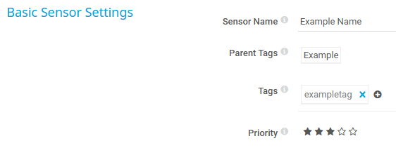
Basic Sensor Settings
The sensor has the following default tags that are automatically predefined in the sensor's settings when you add the sensor:
- plc
- s7
- s7customprocessdatasensor
- siemens
For more information about basic sensor settings, see section Sensor Settings.
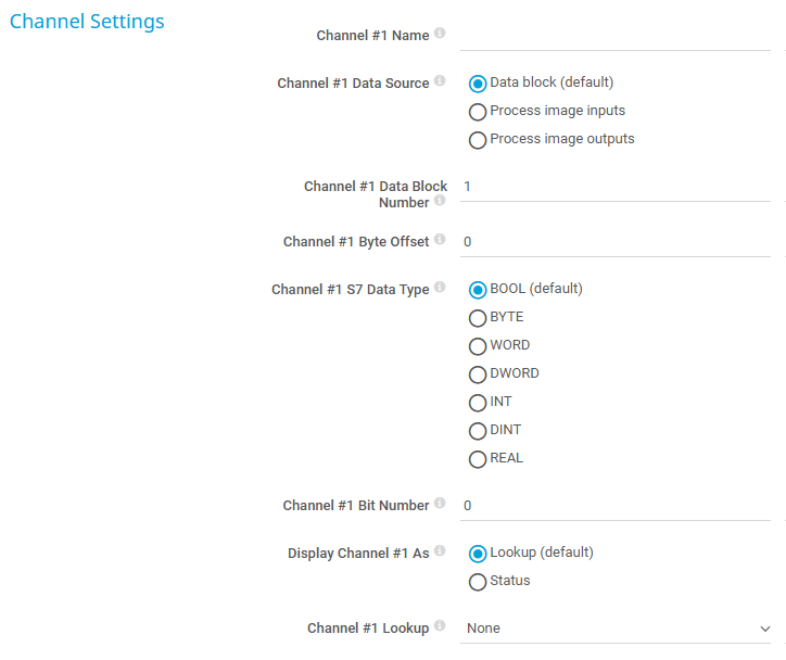
Channel Settings
Setting |
Description |
|---|---|
Channel #x Name |
Enter a name to identify the channel. Enter a string.
|
Channel #x Data Source |
Select where in the PLC the sensor reads the data from:
|
Channel #x Data Block Number |
This setting is only visible if you select Data block (default) above. Enter the number of the data block that you want the sensor to read. For example, for DB10.DBX2.3, enter 10. Enter an integer.
|
Channel #x Byte Offset |
Enter the address of the first byte that you want the sensor to read in the data source. In a data block, the byte offset is relative to the start of the data block. Enter an integer. For example:
|
Channel #x S7 Data Type |
Select the data type that the PLC program uses for the value that you want to monitor:
|
Channel #x Bit Number |
This setting is only visible if you select BOOL (default) above. Enter the number of the bit in the byte that you want the sensor to read. Enter an integer from 0 to 7. For example:
|
Display Channel #x As |
This setting is only visible if you select BOOL (default) above. Select how the sensor shows the value:
|
|
Channel #x Lookup |
This setting is only visible if you select BOOL (default) and Lookup (default) above. Select a lookup file that you want to use with this channel. The lookup must use the value 128 for FALSE and 129 for TRUE. The standard PRTG lookups for Boolean values do not work with this setting. This setting is only visible during sensor creation. If you want to change this setting after sensor creation, use the channel settings. |
Channel #x Status Mapping |
This setting is only visible if you select Status above. Select when the sensor shows the Down or Warning status. Otherwise, the sensor shows the Up status:
|
Display Channel #x As |
This setting is only visible if you select BYTE, WORD, or DWORD above. Select how the sensor shows the value:
|
Channel #x Lookup |
This setting is only visible if you select BYTE, WORD, or DWORD and Lookup (default) above. Select a lookup file that you want to use with this channel. The sensor uses the value that it reads from the PLC as the lookup value. This setting is only visible during sensor creation. If you want to change this setting after sensor creation, use the channel settings. |
Channel #x Unit |
This setting is only visible if you select Integer (unsigned) or Integer (signed) above, or if you select INT, DINT, or REAL as Channel #x S7 Data Type. Select the unit of the value that this channel monitors:
|
Channel #x Custom Unit |
This setting is only visible if you select Custom above. Define a unit for the channel value. For example, enter bar, rpm, or l/min. Enter a string.
|
Channel #x Scale Factor |
This setting is only visible if you select Integer (unsigned) or Integer (signed) above, or if you select INT, DINT, or REAL as Channel #x S7 Data Type. If you want to scale the received data, enter an integer or a floating-point number. If you want to scale up, enter a value over one. If you want to scale down, enter a value below one. Use the default scale factor, 1, to not change the data. For example, if the PLC program stores a temperature of 23.5 °C as 235, enter 0.1.
|
Channel #2 - #10 |
You can define up to 10 channels. You must define at least one channel, so you see all available settings for Channel #1. Specify how to handle all other possible channels:
|

Sensor Display
Setting |
Description |
|---|---|
Primary Channel |
Select a channel from the list to define it as the primary channel. In the device tree, PRTG displays the last value of the primary channel below the sensor's name. The available options depend on what channels are available for this sensor.
|
Graph Type |
Define how this sensor shows different channels:
|
Stack Unit |
This setting is only visible if you select Stack channels on top of each other above. Select a unit from the list. PRTG stacks all channels with this unit on top of each other. By default, you cannot exclude single channels from stacking if they use the selected unit. However, there is an advanced procedure to do so. |



Debug Options
Setting |
Description |
|---|---|
Result Handling |
Define what PRTG does with the sensor result:
|
 This option is not available when the sensor runs on the hosted probe of a PRTG Hosted Monitor instance.
By default, all of these settings are inherited from objects that are higher in the hierarchy. We recommend that you change them centrally in the root group settings if necessary. To change a setting for this object only, click  under the corresponding setting name to disable the inheritance and to display its options.
For more information, see section Inheritance of Settings.
The sensor supports the following S7 data types:
S7 data type |
Size |
Value range |
Shown in PRTG as |
|---|---|---|---|
BOOL |
1 bit |
FALSE or TRUE |
Lookup or status |
BYTE |
8 bits |
0 to 255 (unsigned) or -128 to 127 (signed) |
Lookup, unsigned integer, or signed integer |
WORD |
16 bits |
0 to 65,535 (unsigned) or -32,768 to 32,767 (signed) |
Lookup, unsigned integer, or signed integer |
DWORD |
32 bits |
0 to 4,294,967,295 (unsigned) or -2,147,483,648 to 2,147,483,647 (signed) |
Lookup, unsigned integer, or signed integer |
INT |
16 bits |
-32,768 to 32,767 |
Signed integer |
DINT |
32 bits |
-2,147,483,648 to 2,147,483,647 |
Signed integer |
REAL |
32 bits |
±1.175495e-38 to ±3.402823e+38 |
Floating-point number |
The PLC program identifies each value by its absolute address, for example, DB10.DBX2.3 or I0.2. To configure a channel, split the absolute address into the channel settings:
- I, Q, or DB: The area of the PLC (Channel #x Data Source). If the data source is a data block, the number after DB is the data block number (Channel #x Data Block Number).
- X, B, W, or D: The size of the value. X is a bit, B is a byte, W is a word (2 bytes), and D is a double word (4 bytes). The size determines the possible data types (Channel #x S7 Data Type). Addresses without a size letter, like I0.2, refer to a bit.
- The number before the period, or after the size letter: The byte offset (Channel #x Byte Offset).
- The number after the period: The bit number (Channel #x Bit Number). Only bit addresses have a bit number.
Absolute Address |
Data Source |
Data Block Number |
Byte Offset |
S7 Data Type |
Bit Number |
|---|---|---|---|---|---|
I0.2 |
Process image inputs |
- |
0 |
BOOL |
2 |
IB3 |
Process image inputs |
- |
3 |
BYTE |
- |
IW4 |
Process image inputs |
- |
4 |
WORD or INT |
- |
ID8 |
Process image inputs |
- |
8 |
DWORD, DINT, or REAL |
- |
Q1.1 |
Process image outputs |
- |
1 |
BOOL |
1 |
QB5 |
Process image outputs |
- |
5 |
BYTE |
- |
QW6 |
Process image outputs |
- |
6 |
WORD or INT |
- |
DB10.DBX2.3 |
Data block (default) |
10 |
2 |
BOOL |
3 |
DB10.DBB4 |
Data block (default) |
10 |
4 |
BYTE |
- |
DB10.DBW4 |
Data block (default) |
10 |
4 |
WORD or INT |
- |
DB10.DBD6 |
Data block (default) |
10 |
6 |
DWORD, DINT, or REAL |
- |
The following examples show common use cases and the channel settings that they need:
Use case |
Description |
Channel settings |
|---|---|---|
Door switch |
A safety contact of a fence door that is TRUE if the door is closed. Address: I0.2 |
|
Motor state |
The command that switches a motor on. Address: Q1.1 |
|
Temperature |
A temperature that the PLC program stores as a floating-point number. Address: DB10.DBD0 |
|
Temperature (scaled) |
A temperature that the PLC program stores as an integer in units of 0.1 °C, for example, 235 for 23.5 °C. Address: DB10.DBW4 |
|
Pressure |
The outlet pressure of a pump in bar. Address: DB10.DBD12 |
|
 For more information about how to create a custom lookup, see section Define Lookups.
Which channels the sensor actually shows might depend on the target device, the available components, and the sensor setup.
Channel |
Description |
|---|---|
Downtime |
In the channel table on the Overview tab, this channel never shows any values. PRTG uses this channel in graphs and reports to show the amount of time in which the sensor was in the Down status. |
[Value] |
The value that the sensor reads from the address that you define in the channel settings. The sensor uses the channel name that you define in Channel #x Name. The channel that you define as Channel #1 is the primary channel by default. |
 KNOWLEDGE BASE
What are beta sensors and how can I use them?
What security features does PRTG include?
